Thermal Imaging Cameras: How to Read Specifications

Thermal cameras are specialised sensors that measure the heat radiating from an object. Results are displayed using a coloured image palette.
The design, inner workings and functionality of a thermal imaging camera can vary substantially between brands. To help you determine the difference between models and find the best for your needs, our scientists have compiled a list of the standard terms and definitions you are likely to encounter in thermal imaging camera specifications.
IR Resolution
Resolution is the clarity of a subject and is directly related to the number of pixels a thermal imaging camera has. The higher the number of pixels, the higher the resolution. There are three standards for thermal camera resolution:
- <160 x 120 (19,600 pixels – Low resolution)
- 320 x 240 (76,800 pixels – Medium resolution); and
- 640 x 480 (307x200 pixels - High resolution).
The amount of resolution required depends on your desired application. For example, working on high-risk items such as electrical equipment, you may want a higher resolution camera to zoom in and maintain a nice sharp image while investigating issues.
Thermal Sensitivity (NETD)
Thermal sensitivity describes how sensitive your camera is to temperature changes. Sensitivity will affect the clarity of the subject or item you are troubleshooting. The more sensitive a thermal camera, the greater the definition between hot and cold areas will be. The lower the sensitivity, the more blurring.
The specification for sensitivity is expressed as NETD; this is ‘Noise Equivalent Temperature Difference’. The NETD value is typically expressed in milli-Kelvin (mK). So, the higher the NETD, the less sensitive the camera is to contrasting temperatures, and vice versa. An easy way to remember this is less noise = greater clarity.
Field of View
The field of view of a thermal imager is determined by its lens and defines the area the imager sees at a given moment. The combination of sensor size, lens, and distance to the measured object will determine the smallest surface area discernible by your imager.
Field of view is expressed in angular degrees (not to be confused with temperature). If your application requires you to measure an object from a distance, you will need a camera with a smaller field of view. If you regularly measure up close to objects, a thermal camera with a wider field of view is needed.
Spatial Resolution/Instantaneous Field of View (IFOV).
In addition to the field of view, some thermal imaging camera specifications list the term spatial resolution or instantaneous field of view (IFOV). This term refers to the smallest detail within the field of view visible at a distance. This parameter is measured and displayed in specifications as mRads. Essentially, the smaller the mRad number, the greater the clarity of an image.
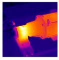
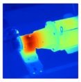
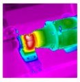
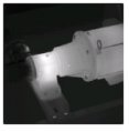
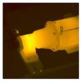
Palette
Palette refers to the colour scheme used to display a thermal image. See Figure 1 (below) for an example of typical palettes available on thermal imaging cameras.
 |
 |
 |
 |
 |
|
Ironbow |
Blue-red |
High-contrast |
Grey |
Amber |
Figure 1 Examples of common colour palettes found on thermal imaging cameras
Distance-to-Spot Ratio
The distance-to-spot ratio is the relationship between an area's size and the thermal imaging camera's distance from the area. Depending on the ratio, the area of the surface measured will grow at a specific rate as the distance increases and smaller as the distance decreases. (See Figure 2 (below) with a 12:1 distance to spot ratio).
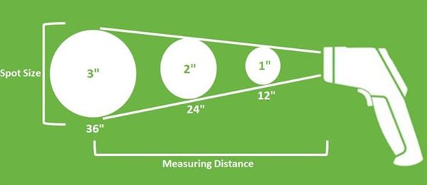
Figure 2 Distance to spot ratio of a Thermal Imaging Camera using a 12:1 ratio as an example.
Emissivity
Emissivity is a measure of how well a surface emits energy as infrared radiation. Emissivity is a scale of 0 to 1, with 0 being a perfect reflector and 1 being an object that doesn’t reflect at all, absorbing all incoming radiation. Many items fall within the emissivity range of 0.95.
The selection of your thermal imaging camera will be dependant on what surfaces you intend to measure. For instance, some thermal imaging cameras have adjustable emissivity covering the entire emissivity range from 0.01 to 1 while others have preset selections, for example, Matte: 95%, Semi-Matte: 80%, Semi-Glossy: 60%, Glossy: 30%.
Figure 3 (below) outlines some everyday objects and their emissivity values.
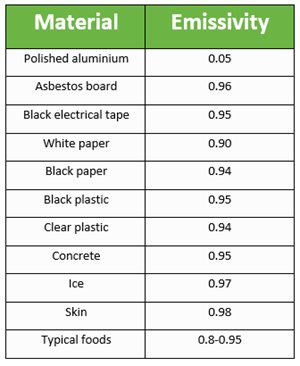
Figure 3 Everyday objects and their emissivity values.
Temperature Measuring Range
The temperature range of a thermal imaging camera specifies a device’s range within which you can be sure of accurate measurements. Specification sheets provide temperature range values (with minimum and maximum temperatures given). If you require a device capable of measuring extremes in temperature, be sure to check that the range of the thermal imaging camera is appropriate.
Accuracy
Accuracy is the closeness of a measurement to a specific value. Thermal imaging camera specifications will express the accuracy of a device as plus or minus a set amount.
Conclusion
Having thermal imaging camera key terms and definitions at your fingertips will help you decode the device’s specifications and support you in selecting the best product for your needs and budget.
Need more advice or assistance finding the best thermal imaging camera for your application? Speak with an Instrument Choice Scientist: Call 1300 737 871 or email [email protected].
Also interesting
The Instrument Choice Team of Scientists regularly reviews new and popular products, so you can make more informed decisions when searching for the perfect scientific instrument for your application.
This review details the Digital Hand-held Pocket Urine Refractometer IC-PAL-10S, a lightweight and powerful handheld refractometer that accurately measures urine specific gravity.
Get our scientists’ review of the Digital Hand-held Pocket Urine Refractometer- IC-PAL-10S

The VDV II Series comprises three easy-to-use cable testers that assess the integrity of copper cables commonly found in domestic, commercial and industrial voice, data or video cabling installations, such as telephone wiring, data network and video/security cabling.
This article details the VDV II Series of Voice, Data and Video Cable Verifiers and compares the three models available.
Read the exclusive VDV II series guide by Instrument Choice
